Overview
This page outlines work I have done on liquid engine design. To put the numerous papers and textbooks I have read on the topic of liquid propulsion to action, myself and others at CU SRL began the liquid development program. The first section is an overview of Jalapeño, a 500 lbf thrust KeroLOX engine which is nearing manufacturing completion. The second section describes Reaper, a 6000 lbf thrust MethaLOX engine currently in development.
Jalapeño Engine
Jalapeño is a pressure fed KeroLOX engine with a 3D printed impinging doublet injector design. Its first iteration is designed to produce 500 lbf of thrust for 8-10 seconds. If this test is successful, we will convert the test set-up into a flight ready state and attempt to fly Jalapeño for the DPF (Dollar Per Foot) Challenge. This challenge allows any student competitors to earn a DPF for ever foot of altitude they are able to achieve off the launch rail with a liquid engine powered rocket.
Injector
The Jalapeno injector utilizes AM for efficient fluid domain design and incredible mass savings. Thanks to Velo3D for printing this for us! AM allows us to implement significant amounts of instrumentation, which will aid in the development process significantly.


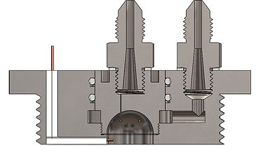
Test Stand and Set-up
This pressure fed test set-up is held structurally by a roughly 21" x 21" x 27" test structure. The red tank shown on the left is the high pressure nitrogen tank. The high pressure nitrogen then passes through a regulator to fill the take directly behind it with low pressure nitrogen. This keeps the whole system at a constant 500 psi for the whole test as the pressure in the high pressure nitrogen tank decreases to pressurize the entire system. After a series of one way valves, check valves, and remotely actuated purge valves, the nitrogen enters both the LOX and Kerosene tanks at 500 psi, forcing the propellants through the injector and into the combustion chamber. Ignition is done externally at the beginning of the test by a slow burning trail of APCP held in the center of the combustion chamber by a 3D printed insert. The insert will be blown out directly after ignition.
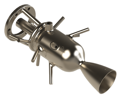
Reaper Engine
Reaper engine is 5000 lbf thrust AM MethaLOX engine. It utilizes two active cooling methods: regenerative and film cooling. We designed this engine using CEA, RPA, MatLab, Solidworks, and a variety of programs for structural, thermo-structural, and CFD analyses. I am also actively developing a turbopump for this engine. The liquid engine team follows the SCRUM engineering development process for continuous progress and innovation on this Reaper and Jalapeño. Note that this project is actively changing and I may not have updated my website to reflect current progress.

CFD analysis in ANSYS Fluent at sea level conditions
Test Stand and Set-up
Reaper will likely be tested vertically at the FAR site in the Mojave desert in California. Though a test is still some time away due to financial restrictions, we hope to reach the test stand during late winter 2021. We chose a vertical test configuration because it will allow for rapid turnaround and launching once we accomplish enough successful testing. If you have any further questions about Reaper, please contact me by my phone or email below! This section is intentionally not descriptive because of ITAR regulations. These images are out of date and will be updated once an AM Reaper design is complete.
Integrated SM Reaper render
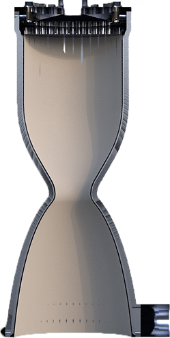

SM Reaper thrust chamber cross section
Turbomachinery
First Turbopump Design
Though I very much dislike this design now, I will show it anyways to show my improvement in later designs. I developed a water turbopump for my graduate rocket propulsion course with similar flow characteristics to the LOX pump I intend to develop after testing this water pump. I did this project in order to learn about turbopump theory, design, manufacturing, and testing so that at the conclusion of this project, I can immediately begin development of cryogenic liquid methane and LOX turbopumps for the Reaper engine. This current turbopump is designed to raise the pressure of 74 gpm of water from 100 psi to 1600 psi at a pump rotational speed of 30,000 rpm. The turbine side of this machine is powered by pressurized nitrogen, which will later be replaced by a fuel rich gas generator when designed for Reaper. The design of this turbopump utilizes CFturbo for fluid domain design and Simerics MP for 3D CFD analysis. Once the internal fluid domain was designed and verified for both the pump and turbine, I exported the fluid domain to SOLIDWORKS and designed a full assembly around the known pump and turbine characteristics.

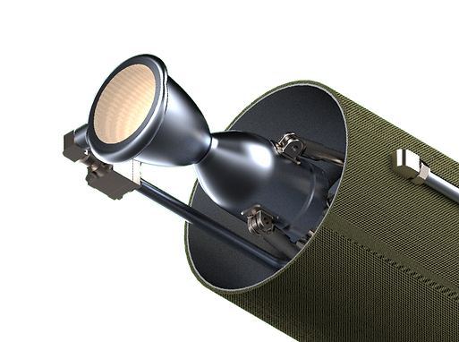
Gas Generator for Reaper Turbopump
Design 1 for SM (not made)
The water turbopump design above, while originally intended for build and testing, did not progress beyond this design because of manufacturing cost barriers and extensive lead times. Instead, the project for my graduate rocket propulsion course became a gas generator for a real pump designed to power Reaper. This gas generator uses a small fraction of the yet-to-be-designed turbopump's high pressure LOX and LCH4 outputs to run, and will drive the turbopump's turbine. The design utilizes a domed injector with dual impingement for optimal mixing and atomization of the propellants. For ignition, the gas generator contains a custom sparkplug igniter. Wires are insulated from the injector metal by a high temperature ceramic and a voltage difference of over 3000 volts is applied using a battery powered boost converter to form a spark across the wire leads. This gas generator design will not be manufactured, as the next iteration described below is superior.

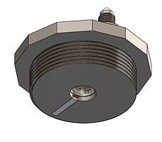


Design 2 for AM
This is the first iteration of the gas generator injector I designed for the AM version of Reaper Turbo. This test version will produce 94 lbf of thrust, has a chamber pressure of 1360 psi, and will be able to run indefinitely. It is printed out of Inconel 718, and has a combustion temperature within the working range of the material. Using AM allows for super efficient fluid domain design with minimal dribble volume as shown in the fluid domain below. This is currently being printed as of February 2, 2021.


Gas generator injector fluid domain
Final design for printing
Translucent view of final design
Cross section of final design
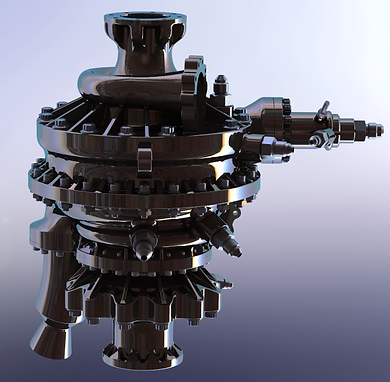
Full MethaLOX Turbopump Design
Over the last year, I designed a full MethaLOX turbopump. This design is being manufactured and moving rapidly towards testing.